Aerospace industry component manufacturing is in a large growth cycle. Advancements in materials and engine efficiency have created clear benefits for replacing a surplus of older aircraft equipment. The advancements cover both the engine and structural components. The demand is so significant that machine tool manufacturers are challenged to supply the equipment fast enough. Since OEMs and suppliers already operate at a high utilisation rate, there has been growth at existing facilities and an increasing number of new certified vendors. The high demand is expected to continue for many years. This challenge can be met by increasing the number of spindles or also by increasing the productivity of tooling, work holding and CAM software solutions. Enhancements to these support technologies can increase the productivity of existing equipment.
CAM Software for Aerospace Machining
There are many CAM software products available and most of these have targeted capabilities. The focus may be on a process such as 5-axis milling, mill/turn, or wire EDM. Or the CAM software may be optimal for applications such as mould and die or aerospace applications.
Not many aerospace machining companies, especially tiered vendors, machine all types of aerospace components. However, some do and certainly, aerospace OEM companies tend to machine a wide array of aerospace parts, even if only for development components.
Therefore, the ideal CAM software for aerospace manufacturers has to excel at high material removal rates and the machining of aluminium structures whilst working well with high precision requirements of compressors and turbines that are often machined with long slender tools.
Requirements for Aerospace Machining
Machining of aerospace components requires excellence by the manufacturer to adopt and carefully follow procedures to ensure quality, repeatability and traceability. The components required in this industry have very stringent and varying requirements. Structural components must be lightweight, generally made from aluminium or composites (may have moulds from aluminium). Engine components and landing gear are generally made of titanium, steel or nickel-based superalloys. These materials focus on strength and temperature resistance. For engine components, titanium is used where possible as the material density is nearly half that of steel or superalloys. It also helps to control weight.
Machining Strategies for Structural Components
High-performance roughing is necessary to bring aluminium blocks or plates to a near-net shape. Up to 90% or more of the block weight may be removed during roughing processes. Not only is this important in typical 3-axis structural components, but it is equally crucial in 5-axis components. Many CAM software programs have a high-performance roughing module. Here, OPEN MIND offers its hyperMILL® MAXX Machining roughing module. This machining approach is based on Celeritive’s Volumill™ kernel but has been extended by OPEN MIND to have an application for 5-axis roughing. In cases of shaped structural components (some wing segments for example or doors), a 5-axis roughing process provides a huge benefit to subsequent machining processes. Following high-performance roughing operations, innovative finishing techniques can have a big impact on results.
The surfaces of standard structural parts are machined with a swarf milling operation, with the side of the cutter aligned to the side of the part. This process enables very good performance, but it is limited to ‘short’ wall surfaces typically up to 50mm in height. For larger wall surfaces, the swarf milling operation may lead to vibration in the cutter or the wall surface, or multiple steps with overlap and inconsistent deflection patterns. In these cases or other cases that do not have ruled surface walls, the next best option is point milling in many passes by using the tip of a ball-nose endmill with a small step-over. This point milling method increases cutting time dramatically.
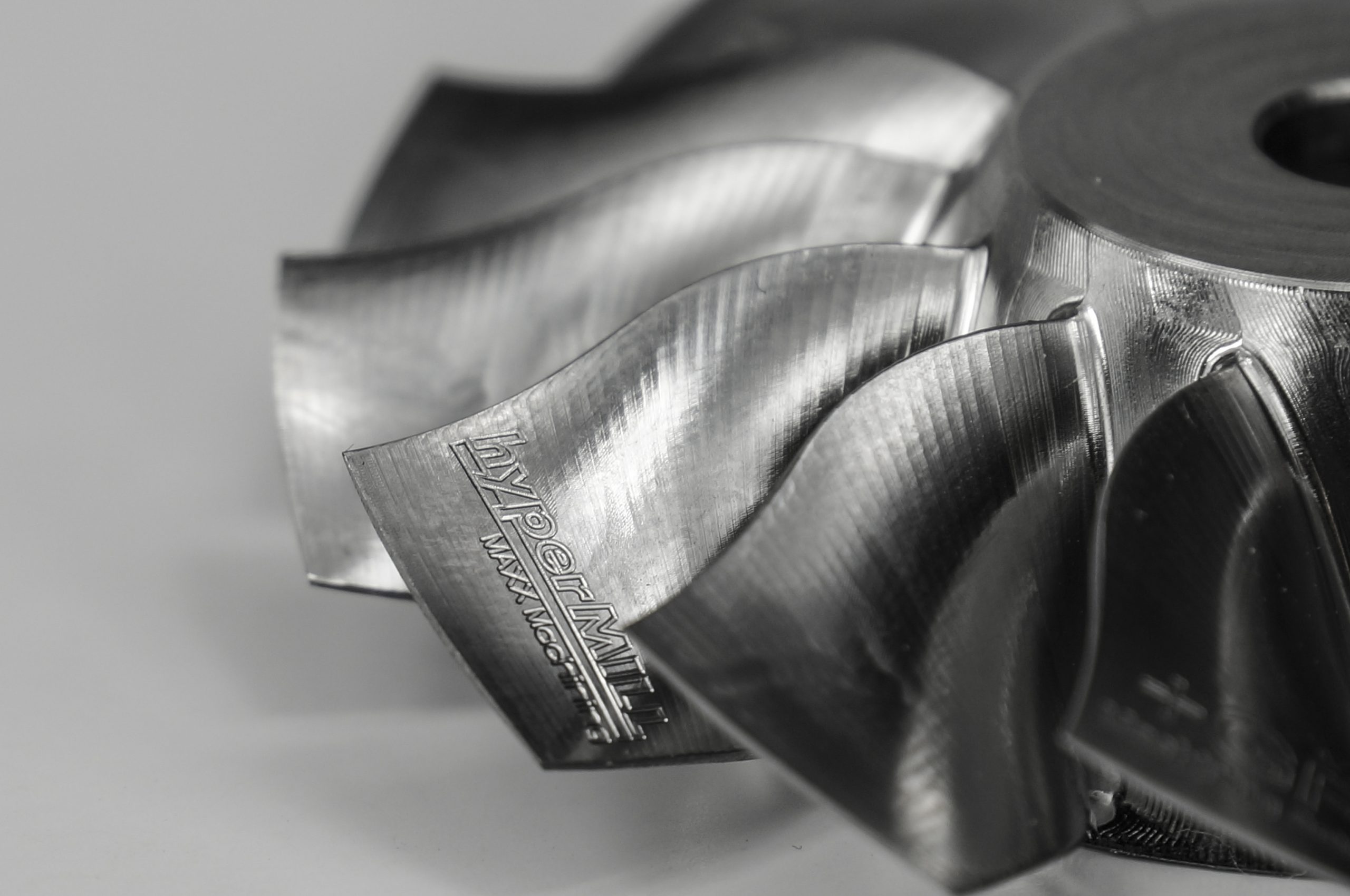
Recent innovations include applying barrel cutter geometry to these surfaces. OPEN MIND’s hyperMILL MAXX Machining finishing approach uses a conical barrel cutter to enable a barrel contact radius of 1000mm or more, thereby producing a wider step-down of 10 to 15 times compared to that of a ball-nose endmill. This enables the cutting time for these surfaces to be reduced by 90% or more. The conical barrel cutter has a large barrel radius ground on a tapered feature, compared to a traditional barrel cutter where the large radius blend is at a tangent to the cutter shank.
hyperMILL MAXX Machining and conical barrel cutters enable a large contact radius and clearance from wall surfaces
The benefit of having the taper angle is that the tool axis can be pulled away from the surface being cut. The result is a shorter and stiffer set-up without interference from the cutter holder. The machining benefits far outweigh the increased cost of conical barrel cutters, especially in aerospace production applications. Though the tangent barrel cutter provides some benefits, the conical barrel cutter is generally superior to enabling a larger barrel radius and allowing shorter cutters without interference from the cutter holder.
Conical barrel cutters exhibit long tool life and very consistent machining performance. In addition, the ball end on the tip of the conical barrel cutter can be used to clean fillets and blend surfaces, using the same cutter.
Machining Strategies for Aerospace Engine Components
Engine components are generally classified into two categories – multi-blade and single-blade. The difference is that multi-blade components are produced as a monolithic shape from one stock while single-blade components are machined as individual airfoils with mechanical attachment features. These are then mechanically assembled to make engine components. Engine components face high temperatures and stresses and potential impact, so materials like titanium, steel and superalloys are used.
An assembled turbine or compressor from machined single blades and a hub disk weighs more than a one-piece compressor or turbine blisk (bladed disk). As engine performance is directly related to its weight, blisks have become more common than single blades in recent generations of engines.
Single-blade machining can start from a rectangular block, cylindrical stock, or near-net forgings. Roughing as always is a critical task to control costs, and also to set up for finishing operations. Due to various starting stock shapes and irregular finishing shapes, stock tracking is essential during roughing operations to avoid wasteful air cuts. As blades can also be twisted, multiple cutting orientations should be used during roughing to leave minimal stock for the finish.
Single-blade finishing is historically performed with ball nose endmills, especially on twisted surfaces and near attachment platforms. Open areas of the blade surface are often cut with a tilted bull-nose cutter. This cutting style gives a large effective radius of curvature and can produce a fine surface finish with fewer passes compared to a ball-nose endmill. As with structural components, recent developments with conical barrel cutters further extend the benefits of using a large contact radius with a stable and controlled machining process.
Finishing of multi-blade components raises additional challenges due to tight blade spacing and requirements for high aspect ratio cutters. The CAM software must possess robust collision detection and avoidance techniques to find a solution to the close spacing between blades.
Due to the small cutter radius that is allowed based on blade spacing and fillet geometry and the fine surface finishes required to meet design specifications, hundreds of passes around the blade may be required to attain the needed surface finish using a ball-nose endmill. Applying these long path lengths against hard metals is time-consuming and leads to cutter wear and concerns for manufacturing consistency. Some engine manufacturers change a cutter for each subsequent blade surface to assure consistency of wear and reduced imbalance of the resulting machined part.
Twisted multi-blade surfaces typically do not allow the use of swarf milling process. Conical barrel cutter solutions are also being applied to achieve cycle time and quality improvements. The larger step-over for conical barrel cutter processes means less overall path length and tool wear compared to ball nose endmills.
Both single-blade and multi-blade components can be classified with feature-based and family-of-parts (macro) programming. In both cases, there are repeated geometry selections of curves and surfaces. These are more complex than typical holes and pockets but can equally be represented by feature definitions. Re-using best practices for materials and tooling including feed rate and spindle speed, holders, step-down, step-over and more, can be useful when programming multiple parts. By having a comprehensive family-of-parts strategy, the programming effort can be reduced over many parts while achieving high productivity results.
CAM software has a large influence over machine tool performance, so users can gain benefits by selecting the proper CAM software for the application at hand. The most advantageous CAM software is continually evolving with each new version release to offer enhancements and innovations which keep up with the requirements of aerospace manufacturing.